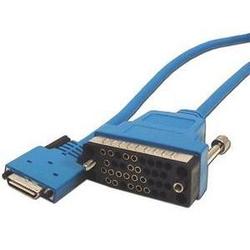
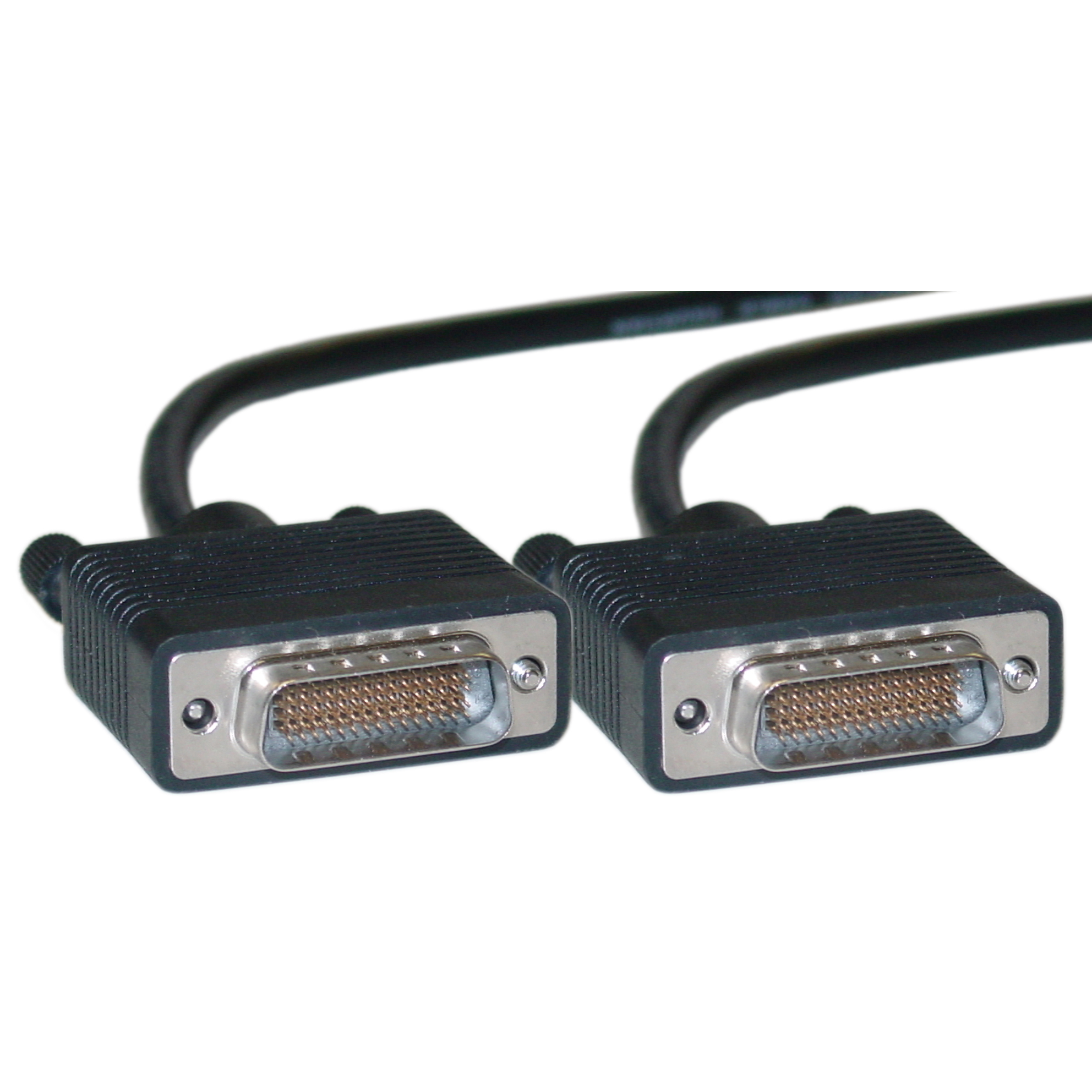
Dce And Dte Serial Cable
Example cables for connection from a PC to various Lantronix products with DB connectors are provided near the end of this FAQ Background: When RS232 was developed the idea was that there would be 2 kinds of devices, DTE (Data Terminal Equipment) and DCE (Data Communications Equipment). Everything would use DB25 connectors and everyone would always connect a DTE to a DCE using a straight-through cable and everything would be easy.
However, as time went by folks wanted to connect two DTEs (or two DCEs) to each other, and connectors started being used, so alternative cable wirings were required. There are no hard and fast rules but in general a DTE will have a male DB25 or possibly a male DB9 connector and a DCE will have a female DB25 or DB9. Other connectors may be used but these are the most common. A typical DTE is a serial port on a terminal, a Com port on a PC or the serial port on an MSS100. A typical DCE is the serial port on a modem or on a UDS-10, UDS100 or UDS1100. If you're connecting a DB25M DTE to a DB25F DCE (an MSS100 to a modem for example) you can use a straight-through cable, i.e.
Software camera hp g42. Examples: 'LaserJet Pro P1102 paper jam', 'ProBook 4430s bios update' Need help finding your product name, number or serial number? - Examples: “SL-M2020W/XAA” • Include keywords along with product name.
Find great deals on eBay for dte serial cable. Shop with confidence.

Pin 1 wired to pin 1, pin 2 wired to pin 2, etc. Because of this DTE connectors are labeled according to the signal on the pin, DCEs are labeled according to the signal that should be coming from the DTE. In other words a DCE and DTE are labeled identically even though the direction of their signals are opposite. The most common DB25 pinout is: 1 Protective ground 2 Transmitted data (Out) (TD or TXD) 3 Received data (In) (RD or RXD) 4 Request to send (Out) (RTS) 5 Clear to send (In) (CTS) 6 Data set ready (In) (DSR) 7 Signal ground (SG) 8 Carrier detect (In) (CD or DCD) 20 Data terminal ready (Out) (DTR) Originally all 25 pins of a DB25 were used but today the above pins are usually the only ones used.

The most common pinout for DB9 serial connectors is: 1 Carrier detect (In) (CD or DCD) 2 Received data (In) (RD or RXD) 3 Transmitted data (Out) (TD or TXD) 4 Data terminal ready (Out) (DTR) 5 Signal ground (SG) 6 Data set ready (In) (DSR) 7 Request to send (Out) (RTS) 8 Clear to send (In) (CTS) 'Straight-through' cable So a cable for a connection from a DB25 DTE to a DB25 DCE is wired: DTE DCE DB25M DB25F DB25M DB25F TXD 2-2 TXD RXD 3-4 RTS CTS 5-20 DTR To connect a DB9M DTE (e.g. The Com Port on a PC) to a DB25F DCE (e.g.
Dce Dte Serial Cable

Attention, Internet Explorer User Announcement: Jive has discontinued support for Internet Explorer 7 and below. In order to provide the best platform for continued innovation, Jive no longer supports Internet Explorer 7. Jive will not function with this version of Internet Explorer. Please consider upgrading to Internet Explorer 8, 9, or 10, or trying another browser such as Firefox, Safari, or Google Chrome. (Please remember to honor your company's IT policies before installing new software!).